The whole system designed in this scheme focuses on the realization principle of the signal acquisition module and the mechanical structure that affects the measurement accuracy. The solution of the angle value is solved by the microprocessor, and the software algorithm is written on the basis of this. The experiment proves that the accuracy of the angle sensor designed by this scheme can reach 0.5°, which can be widely used in industrial fields such as automobiles and motors to meet the required technical specifications.
1 Introduction
Angle sensors are widely used in automotive, mechanical, aerospace, aerospace, marine, industrial automation and other fields. It is mainly divided into contact type and non-contact type. Due to the increase of the use time of the contact type angle sensor, there are disadvantages such as mechanical wear, reduced precision, frequent maintenance or even replacement of new equipment, which not only increases the production cost but also increases the production cost. It is easy to make the quality of the device under test not guaranteed, and the non-contact angle sensor overcomes these disadvantages. Commonly used non-contact angle sensors are photoelectric and magnetoelectric. Although the photoelectric type is higher in precision than the magnetoelectric type, it is environmentally demanding and has poor seismic resistance, so it is not suitable for industrial environments where the environment is complicated. Based on these problems, a magnetoelectric-based angle sensor is designed, which has the advantages of low cost, high anti-interference, and resolution within 0.5°.
2. System overall design principle
The whole system consists of four parts, which are power module, magnetic sensor signal acquisition module, microprocessor module and signal output module. The hardware block diagram is shown in Figure 1.
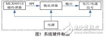
The magnetic sensor signal acquisition module mainly detects the change of the angle through the integrated chip integrated with the dual-axis Hall element, and outputs it to the microprocessor in the form of an analog signal or a digital signal. After a certain encoding and decoding, the microprocessor outputs the industry. The voltage or current signal is used, or the digital signal is output by serial communication. In order to reduce the complexity of the system and the source of error, the signal acquisition unit selected Melexis' MLX90316 chip. It belongs to the CMOS Hall sensor, can output the angular position information corresponding to the magnetic field parallel to the surface of the chip, and output the digital signal by serial communication of SPI, eliminating the A/D conversion circuit, which greatly reduces the The complexity of the system design. The microprocessor module uses Freescale's MC9S08DZ60, a 16-bit microprocessor with small size, low cost, low power consumption and many external interfaces.
It has 24 12-bit A/D channels, Controller Area Network (MSCAN), Serial Peripheral Interface Module (SPI), Serial Communication Interface (SCI/USART), Inter-Integrated Circuit Bus (IIC) and other peripherals. The digital interface is ideal for digital signal communication with the outside world.
3. Mechanical structure design
The mechanical structure of the angle sensor is mainly composed of three parts, which are a rotating shaft, a magnet and a detecting circuit. Its structure is shown in Figure 2.
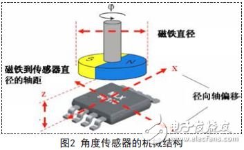
The mechanical deviation of the rotating shaft, magnet and sensor position will determine the accuracy of the system measurement. Mechanical errors can result in additional voltage offsets, phase shifts, amplitude variations, and nonlinear errors compared to ideal Sine and Cosine output curves.
The lower limit of the magnet to sensor wheelbase is determined by the saturation effect (electrical or magnetic field), and the upper limit is determined by the signal-to-noise ratio, the ratio of the signal to the offset voltage.
Due to the mechanical wear caused by the rotation of the rotating shaft and the position of the shaft offset caused by the vibration, the angular output signal will be nonlinear. Figure 3 reveals the angular error caused by the nonlinearity of the magnet axis.
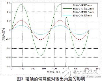
It can be seen from Fig. 3 that the larger the deviation of the axis of the magnet is, the larger the angular error of the final output is. Therefore, to ensure the accuracy of the output angle, the deviation of the axis of the selected magnet should satisfy a certain degree of concentricity.
Innovation of MCU control system was adopted to realize stepless, four color temperature of light output, single control/group control, timer switch, smartprofiles, ect
Wireless control, easy to install. 86 controller, light sensor is compose of simple control system can compatible with our remotecontrol.
CCT Changeable & Dimmable Downlight
Dimmable LED Downlights,CCT Changeable Downlight,CCT Dimmable Downlight,Cut Out 160-180mm Downlight
SHENZHEN KEHEI LIGHTING TECHNOLOGY CO.LTD , https://www.keheiled.com